Modded my 3 week old 430EX II yesterday. Its actually easy and there's plenty of room to put the 3.5mm socket. There's very little room in the foot compartment, so after a few fiddling around, I managed to find a sweet spot to put the socket. Its on the left side upper corner of the flash' body - flash facing you.
The most difficult task in doing the mod is disassembly. It's not really that difficult, but just because of a little clip on one side of the flash, its almost impossible not to break it. Its very well hidden (thank you Canon engineers) that I never expected it to be there at all.
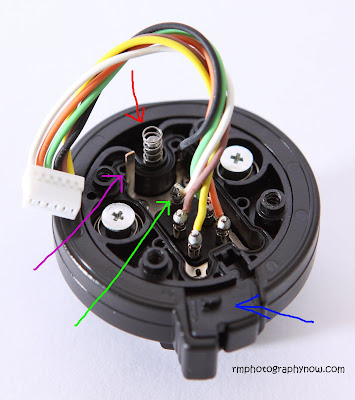
First thing to do is remove the 4 screws of the flash's foot. You will see colorful wires attached from the shoe to the bottom PCB of the flash. They are attached by micro or nano connectors (whatever they are called) just gently pull from the base of the connector to disconnect, now the shoe is completely free. Be very careful as there are two loose springs that can jump off (see pics below). Twist the flash head up and turn 90 degrees, you will see 4 screws where the markings in degrees are. Do you see them? You only need to remove the screws holding the front part of the body (where the AF assist beam is attached). Now everything will be loose and here comes the difficult part... The pic below shows where the nasty bit of platic and metal are located. Just imagine how they are clipped together and do your magic.
Above: Pink arrow shows the bracket mount - who uses this mount? It could have been more useful if they put a sync port or just left the space for modding.
Green arrow shows the nasty retaining metal clip. Blue arrow is where the broken little plastic bit resides, easily fixed with araldite adhesive. The plastic bit is actually a hook.
Now front plate is removed, you can start making the hole for the 3.5mm socket. Here's a pic of my drilled front plate:
You can actually drill a bit higher which is a better position so you don't have to shave a bit off the 3.5mm socket later on. Why? Because I found out that the socket slightly touches part of the flash's PCB.
Before mounting the socket, its better to solder 2 pieces of wires first. Positive end of the socket connects to the positive terminal of the flash's shoe, and negative end of the socket to the negative terminal of the shoe.
Let's look at more pics:
Above: Showing the innards of the 430EX II flash and a little illustration to show you where the 3.5mm socket and wires will be.
X = is where the hole is drilled for the socket. Y = is where its housed. Blue lines show where the 2 wires will be sitting.
Above: The finished product. To make it easier to solder the 2 wires to the shoe's terminals, you need to disassemble the foot. It breaks down in three parts and you only need to undo 4 screws (look at pics below). Green arrows show Positive to positive terminals, Blue arrows - negative terminals, Pink arrows show the hardened araldite adhesive I used to fix the wires and the socket for added stability.
Above shows the flash's foot. I have already removed the base plate by undoing 4 screws (see picture of base plate below). Red arrow shows the spring of the locking pin, Blue arrow shows the locking mechanism and inside it hides a small little tiny minute spring. The locking mechanism just sits on top of the foot, sorry forgot to take pic of it.
Green arrow points to the possitive terminal connected to a white cable (connect the positive terminal from the socket here) , and Pink arrow is an alternative and better place to connect the negative terminal from the socket.
Above pic shows the shoe base. Blue arrows show where the first four screws (beginning) were removed. Red arrows show where I removed the four screws that hold the foot (previous pic).
And now presenting the star of the day!
The RF-602 trigger which I use now has a hotshoe and a wake up facility that actually works when my 430EX II snoozes. Though IMHO its well built, I still wouldn't trust it. How about the wake up function which is disabled when using just the cable to trigger your flash? I don't really need wake up function as I leave my flash on all the time when I'm using it. It's also reported that wake up function doesn't always work on some flashes like SB800.
Some quick test shots using RF-602 with cable:
Test video with machine gun mode


Nice mod, but I was wondering why you did it if you already had RF 602 radio transmitters?
ReplyDeleteHi thanks, I did the mod because I don't trust the RF602's hotshoe, and I don't want to break it either.
ReplyDeleteHI, I see you are using the standard cable with the rf602 (3.5mm) and an adapter from PC Sync to 3.5mm
ReplyDeleteCan you tell me where you got the adapter from as I have been looking for one for a while, otherwise I am going to buy the RF602 - PC Sync Cables
Thanks
@Kevin - there's no PC sync - the adapter is a reducer which came with the set of triggers.
ReplyDeleteTHANK YOU!!! So So much. That picture 5 of 9 of the inside of the 430EXII shoe assembly showed exactly where that spring and rod went... you saved my rear big time! I can't thank you enough. It's the only picture out there and this was incredible. Happy holidays to you and your family! SP
ReplyDelete