Hi all,
First and foremost, before doing this mod, I did a lot of reading about different kinds of mods you can do to increase the triggering distance of the Cactus V2s Wireless Trigger otherwise known as Poverty Wizard!
Before anything else, I would like to say I bought this Trigger/Receiver because I can't afford PW's, Skyports, Radio Popper, or any other high priced alternative.
I have read the following forum threads/blogs:
Now its time to do the mod!
I need to say the best Mod I have seen is in link no. 7 above. Cosmetic and flexibility wise (I'm talking about his Trigger mod only), it is a clear winner because the finished product looks good, and you can remove the antenna when storing the trigger, but if I think of the cost of materials, especially I'm here in the UK (at the moment) where taxes are high, its not a very good option for me.
There were some peeps reporting that 1/4 wavelength antenna connected to the PCB of the trigger (especially the author of no. 7) with 1 inch wire works, some people disagree saying it doesn't work, and they use about 6.5inches or shorter/longer wire to connect the antenna to the PCB.
Other people use 1/4 wavelentgh of coiled wire inside the trigger and report it works as well.
Someone also used an old cordless phone's antenna, an old mobile phone's antenna, etc. The list goes on!
Anyway its time for me to decide on which one to follow! I was really leaning towards the 433Mhz antenna mod described in link no. 7 above. I was about to hit the button last night, but my undecided mind said the cost is almost the same for another V2s receiver.....
Hmmm.... if others used the coiled copper wire inside, maybe I should try that!
I didn't have any at home, but I found an old Cat5e cable that came with my wireless router!
I immediatley stripped it and cut out 6.82 inches long wire.
Hang on, by reading all of the 7 links above, most people attach antenna/cable to the right of the PCB (assuming the trigger is facing you), but some people attach it to the left. I have also read some people rationalizing that when you attach the antenna to the right, you have to cut the tracing to the left.
And if you decide to attach the antenna to the left, then you have to deduct the tracing's length which is about 1.25 inches from the wire that you are going to use as antenna. So I decided to follow the latter, 6.82 - 1.25 = 5.57 inches!
Cut... solder... test!
I was shocked, its not stable, its not as stable as before I soldered the antenna. It can trigger the receiver but intermittently! That's bad!
But there was a discussion in post no.7 that the 433mhz antenna with 1 inch wire doesn't work (with some people), instead, solder another 1/4 wavelength of copper wire from the PCB to the end of the 433Mhz antenna to make it 1/2 wavelenght.
That's where I got the idea, to make a 1/2 wavelenght of coiled copper wire. To make the story short, heres the calculation: 13.64inches - 1.25 inches (PCB trace) = 12.39 inches copper wire. Coiled copper antenna soldered to the left.
And the result was fantastic! I can trigger the flash when I'm standing about 30 feet outside my house and the flash way inside the house. I wasn't able to do that before the mod!
Above, after trigger mod, same location as before the mod, but receiver was way inside the house approx. 30ft. away from original location of receiver in the first picture (which was deleted for security reasons), and I was stood a bit further back!
The photo was taken around 10pm (you see I'm still out and I can't sleep because of this mod)
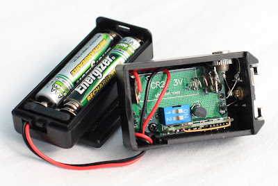
Above is the finished product!
I still have to do more tests to confirm that the mod works 100%, but at this point in time, I consider it a success!
Update April 23, 2008
Above is my distance test with my friend Michael Casanova holding the flash!
Can you see him and the people walking opposite?
The picture was shot using 400D with 24-105 L zoomed out @24mm.
I'm 5'-5" and thats 100 paces, sorry I don't have a long measuring tape.
View similar entry in my flickr
Happy modding and Good Luck!
Update May 26, 2008
Notes:
1. If you only have 1 Cat5e cable, don't chop it as you may need it to configure your wireless router.
2. If after doing this mod, you can trigger only 1 receiver, or you can trigger intermittently, or can't trigger at all, your battery might be the cause.Please note that the battery that came with the trigger/receiver is only meant for testing (according to Gadget Infinity) so please change your batteries.
3. I have found that when you are testing for range, a reliable way to test is by mounting the transmitter on your camera and pressing the shutter (like taking actual pictures) and not by pressing the test button on the transmitter.
4. Sometimes the battery contacts of the V2s receiver is somewhat wonky and the battery doesn't fit properly, therefore no proper contact with battery- so its worth checking this as well.


