Sunday 12 December 2010

430EX II Mod Part 2

ATTENTION: You will void your warranty, may ruin your flash, and you run the risk of electric shock/electrocution by doing this mod. By following the guide below, you do so at your own risk.


After the success of my 430EX II sync jack mod, I'm pleased to be able to do a "swivel mod" which this blog is all about. Thanks to this thread at POTN for the guide.

The problem with the 430EX II is when one is shooting in portrait mode, the flash head can only swivel to 90 degrees to the right (pointing to the ceiling). Sometimes we want to point the flash further to the back (past 90 degrees) to achieve a more natural looking lighting which is not possible without using some hotshoe adapter or flash bracket with ETTL cord.

The 430EX II normally swivels up to 180degrees to the left, and 90degrees to the right. What we want to do is to reverse the swivel, 180degrees to the right and 90 + 30ish to the left (see first 2 pictures below).

Click on the image/s to enlarge.


You need to open up your flash by removing 6 screws. Its better to start off with the
two screws that hold the front body. They can be accessed by swivelling the head to the right/left. They are on the top of the main body of the flash. You want the ones that hold  the front body. Once both screws are out, then you can remove the 4 remaining screws at the foot of the flash.

The OP at POTN said he was able to wiggle the head off by pushing the release button and wiggling it while spreading the housing. I was able to do that but found it difficult, so I separated the front body and broke the plastic that attaches to the metal clip again.

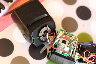
Once the head is out, you will see a metal ring attached by four screws. Note the position of the ring, its tab, and the ring's slit (6 o'clock). The ring's slit fits on a plastic ridge (see green arrow in picture below). This plastic ridge is what we will file off so we can rotate the metal ring from the 6 o'clock position (position of plastic ridge, see green arrow in pic below) to 9 o'clock (90degrees).

Picture below shows the plastic ridge we need to remove. Note its position now, its at 12 o'clock because I have turned the head.

Always remember to protect your flash from unnecessary/unwanted scratches.
In the below picture, the ridge is now gone. Thanks to my £1 set of files bought from my local Pound shop.

 The pic below shows the metal ring's tab already reduced. I have filed off more than
half of it. This will allow the flash to swivel around 25-35 degrees more to the left. You don't really need to do this if you only want the 90degrees swivel but it only takes a few more minutes to do it and you'll never know when you'll need the extra degrees of rotation.
 

Now we can see the new position of the metal ring. Re-assembly should be easy. Just be carefull not to catch any wires.

Maximum swivel position before mod

Maximum swivel position after mod

Good luck and Happy Modding

Friday 6 November 2009

430EX II Mod

ATTENTION: You will void your warranty, may ruin your flash, and you run the risk of electric shock/electrocution by doing this mod. By following the guide below, you do so at your own risk.


Modded my 3 week old 430EX II yesterday. Its actually easy and there's plenty of room to put the 3.5mm socket. There's very little room in the foot compartment,  so after a few fiddling around, I managed to find a sweet spot to put the socket. Its on the left  side upper corner of the flash' body - flash facing you.

The most difficult task in doing the mod is disassembly. It's not really that difficult, but just because of a little clip on one side of the flash, its almost impossible not to break it. Its very well hidden (thank you Canon engineers) that I never expected it to be there at all.

First thing to do is remove the 4 screws of the flash's foot. You will see colorful wires attached from the shoe to the bottom PCB of the flash. They are attached by micro or nano connectors (whatever they are called) just gently pull from the base of the connector to disconnect, now the shoe is completely free. Be very careful as there are two loose springs that can jump off (see pics below). Twist the flash head up and turn 90 degrees, you will see 4 screws where the markings in degrees are. Do you see them? You only need to remove the screws holding the front part of the body (where the AF assist beam is attached). Now everything will be loose and here comes the difficult part... The pic below shows where the nasty bit of platic and metal are located. Just imagine how they are clipped together and do your magic.

Above: Pink arrow shows the bracket mount - who uses this mount? It could have been more useful if they put a sync port or just left the space for modding.
Green arrow shows the nasty retaining metal clip. Blue arrow is where the broken little plastic bit resides, easily fixed with araldite adhesive. The plastic bit is actually a hook.

Now front plate is removed, you can start making the hole for the 3.5mm socket. Here's a pic of my drilled front plate:

You can actually drill a bit higher which is a better position so you don't have to shave a bit off the 3.5mm socket later on. Why? Because I found out that the socket slightly touches part of the flash's PCB.

Before mounting the socket, its better to solder 2 pieces of wires first. Positive end of the socket connects to the positive terminal of the flash's shoe, and negative end of the socket to the negative terminal of the shoe.


Let's look at more pics:
Above: Showing the innards of the 430EX II flash and a little illustration to show you where the 3.5mm socket and wires will be.
X = is where the hole is drilled for the socket. Y = is where its housed. Blue lines show where the 2 wires will be sitting.


Above: The finished product. To make it easier to solder the 2 wires to the shoe's terminals, you need to disassemble the foot. It breaks down in three parts and you only need to undo 4 screws (look at pics below). Green arrows show Positive to positive terminals, Blue arrows - negative terminals, Pink arrows show the hardened araldite adhesive I used to fix the wires and the socket for added stability.


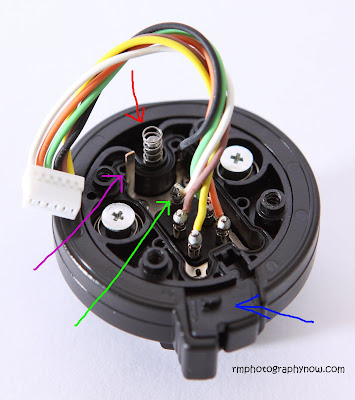
Above shows the flash's foot. I have already removed the base plate by undoing 4 screws (see picture of base plate below). Red arrow shows the spring of the locking pin, Blue arrow shows the locking mechanism and inside it hides a small little tiny minute spring. The locking mechanism just sits on top of the foot, sorry forgot to take pic of it.
Green arrow points to the possitive terminal connected to a white cable (connect the positive terminal from the socket here) , and Pink arrow is an alternative  and better place to connect the negative terminal from the socket.


Above pic shows the shoe base. Blue arrows show where the first four screws (beginning) were removed. Red arrows show where I removed the four screws that hold the foot (previous pic).


And now presenting the star of the day!

The RF-602 trigger which I use now has a hotshoe and a wake up facility that actually works when my 430EX II snoozes. Though IMHO its well built, I still wouldn't trust it. How about the wake up function which is disabled when using just the cable to trigger your flash? I don't really need wake up function as I leave my flash on all the time when I'm using it. It's also reported that wake up function doesn't always work on some flashes like SB800.


Some quick test shots using RF-602 with cable:


Test video with machine gun mode


Monday 2 November 2009

Yongnuo RF-602 Review


I just received my new Yongnuo RF-602 Flash/Camera Trigger today.
First set came with 1 Transmitter, 1 Receiver, and 2 cables, one for triggering the camera and another for triggering studio strobes which can also be used for triggering any flash that accepts 3.5mm jack using the supplied 6.35mm to 2.5mm adapter. The 2 extra receivers came with their own boxes with no cables included.

The Transmitter has a metal shoe that looks like  my 580EX II and 430EX II's. It has 5 contacts though I'm not sure if they are all active. The PC sync port is a screw-lock type. The push button has two steps, half press and full press. Battery door is better and easily accessible which is located at the back of the transmitter and uses CR2 battery. It has no On/Off switch. Underneath the transmitter lies the 4 channel selector.

The Receiver has a metal hotshoe mount, the back has a proprietary port for connecting both included cables for camera and flash triggering. At the bottom of the receiver lies a plastic foot which has 1/4" screw mount and allows mounting on a flash stand or tripod. This receiver uses x2 AAA batteries and can be easily accessed by sliding the battery cover. On/Off switch and 4-channel selector are both at the top of the receiver.

First impression - WOW! Both Transmitter and all Receivers look well built. They feel solid to the touch, and no misaligned gaps/joints, battery compartments are secure and tight not like the Cactus V2s.

Flaws - as seen in the pictures below, the on/off switch on the receiver can be obstructed by the mounted flash. As a result, one has to unmount the flash to switch the receiver on or off. They should have moved the switch further at the front or swapped places where the word "Yongnuo"  is. . The receiver's foot should also have a lock so it won't slip off when mounted on another hot shoe or cold shoe or flash stand.

The Transmitter's battery door is not removable, instead its retained by two little plastic recess on each side of the door on one end. This is a fragile part of the Transmitter. The door should have been made fully removable just like the one on the Receiver.

As mentioned earlier, the set came with a Receiver to strobe cord which is 6.35mm I think with a 6.35mm to 3.5mm reducer. It should have been the other way around. And I can't find any cord with a direct 3.5mm jack. I'm stuck with the cumbersome cord with reducer to use with my modded flash. This is also why I hate the proprietary yongnuo connector. If they used stereo jack, it would be easier to DIY. It's all about money ey! I wouldn't mind paying a few more quid if they used stereo jack.

To me, these are just minor shortcomings of the RF-602 considering its price tag. And as long as it syncs to my camera's maximum flash sync speed (non HSS of course) which was not possible with my then sold Cactus V2s, maintain long triggering range (shame on you PW Flex!!!), and hopefully doesn't go kaput after a few months as some people report, I'm very much content with my purchase.


Above: 430EX II mounted on RF-602 Receiver


Above: 580EX II mounted on RF-602 Receiver


Above: RF-602 Receiver mounted on flash stand


Tests with my 580EX II, 430EX II, (battered) Sigma 500 DG Super, and Yongnuo YN462. They all fire and am happy to say, I can get the maximum advertised triggering speed of 1/250s  on a Canon 50D without banding !!! I've never experienced any misfiring or missed fire with the 100+ shots I took. Wake up function also works with both 580EX II and 430EX II.

Testing my 580EX II mounted on the receiver's hotshoe, I can trigger it as far as 150 paces. With my 430EX II, I can go as far as 200+ paces - I've ran out of space. When I try to trigger them together, they both fire upto 150 paces, when I exceed that, the 430EX II won't fire. That's weird isn't it? It should be the 580EX II that shouldn't fire. What's even weird is when I try to trigger my 500DG Super with any of my Canon flashes, it fires but it's out of sync - it fires late (and I've already swapped the receivers around just to make sure one of them's not the culprit). But when I trigger it on its own, its ok and I can go as far as 200 paces. Another weird behaviour of my 500DG Super when used with RF-602 receiver is it fires just like when set to stroboscopic mode when I use slow shutter speed.

So far I'm happy with my new set! Comparing it with my then modded Cactus V2s, the new RF-602 is an upgrade in every respect!


Above:  my battered 500DG Super with the RF-602 receiver using the included cable...


Above: my 50D's "self portrait" with RF-602 receiver as shutter trigger


Above 50D with 580EX II at 1/250sec (highest sync speed). Below is at 1/320sec.


Here's a short video showing wake up function and why Yongnuo should have added a shoe lock.


And another with Transmitter mounted on camera


Machine gun mode


Wednesday 29 October 2008

Gadget Infinity Cactus V2s Receiver Battery Mod

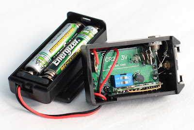
I've tried all sorts of Cactus Receiver mods. I was supposed to post this a while ago with my Cactus Trigger Mod where you can see another trigger mod using 3.5mm mono plug. Here it is now, the easiest, simplest and most cost effective mod I've done, no drilling and glue-ing involved. Just 2 solder points and and velcro between battery compartment and receiver and its done.

I'll let the pictures do the talking...


Same entry in my flickr blog


Monday 21 April 2008

Gadget Infinity Cactus V2s Trigger Mod

Hi all,

First and foremost, before doing this mod, I did a lot of reading about different kinds of mods you can do to increase the triggering distance of the Cactus V2s Wireless Trigger otherwise known as Poverty Wizard!

Before anything else, I would like to say I bought this Trigger/Receiver because I can't afford PW's, Skyports, Radio Popper, or any other high priced alternative.

I have read the following forum threads/blogs:

Now its time to do the mod!
I need to say the best Mod I have seen is in link no. 7 above. Cosmetic and flexibility wise (I'm talking about his Trigger mod only), it is a clear winner because the finished product looks good, and you can remove the antenna when storing the trigger, but if I think of the cost of materials, especially I'm here in the UK (at the moment) where taxes are high, its not a very good option for me.
There were some peeps reporting that 1/4 wavelength antenna connected to the PCB of the trigger (especially the author of no. 7) with 1 inch wire works, some people disagree saying it doesn't work, and they use about 6.5inches or shorter/longer wire to connect the antenna to the PCB.
Other people use 1/4 wavelentgh of coiled wire inside the trigger and report it works as well.

Someone also used an old cordless phone's antenna, an old mobile phone's antenna, etc. The list goes on!
Anyway its time for me to decide on which one to follow! I was really leaning towards the 433Mhz antenna mod described in link no. 7 above. I was about to hit the button last night, but my undecided mind said the cost is almost the same for another V2s receiver.....

Hmmm.... if others used the coiled copper wire inside, maybe I should try that!
I didn't have any at home, but I found an old Cat5e cable that came with my wireless router!
I immediatley stripped it and cut out 6.82 inches long wire.


Hang on, by reading all of the 7 links above, most people attach antenna/cable to the right of the PCB (assuming the trigger is facing you), but some people attach it to the left. I have also read some people rationalizing that when you attach the antenna to the right, you have to cut the tracing to the left.

And if you decide to attach the antenna to the left, then you have to deduct the tracing's length which is about 1.25 inches from the wire that you are going to use as antenna. So I decided to follow the latter, 6.82 - 1.25 = 5.57 inches!

Cut... solder... test!

I was shocked, its not stable, its not as stable as before I soldered the antenna. It can trigger the receiver but intermittently! That's bad!

But there was a discussion in post no.7 that the 433mhz antenna with 1 inch wire doesn't work (with some people), instead, solder another 1/4 wavelength of copper wire from the PCB to the end of the 433Mhz antenna to make it 1/2 wavelenght.

That's where I got the idea, to make a 1/2 wavelenght of coiled copper wire. To make the story short, heres the calculation: 13.64inches - 1.25 inches (PCB trace) = 12.39 inches copper wire. Coiled copper antenna soldered to the left.

And the result was fantastic! I can trigger the flash when I'm standing about 30 feet outside my house and the flash way inside the house. I wasn't able to do that before the mod!


Above, after trigger mod, same location as before the mod, but receiver was way inside the house approx. 30ft. away from original location of receiver in the first picture (which was deleted for security reasons), and I was stood a bit further back!
The photo was taken around 10pm (you see I'm still out and I can't sleep because of this mod)


Above is the finished product!
I still have to do more tests to confirm that the mod works 100%, but at this point in time, I consider it a success!

Update April 23, 2008

Above is my distance test with my friend Michael Casanova holding the flash!
Can you see him and the people walking opposite?
The picture was shot using 400D with 24-105 L zoomed out @24mm.
I'm 5'-5" and thats 100 paces, sorry I don't have a long measuring tape.


View similar entry in my flickr

Happy modding and Good Luck!


Update May 26, 2008

Notes:
1. If you only have 1 Cat5e cable, don't chop it as you may need it to configure your wireless router.
2. If after doing this mod, you can trigger only 1 receiver, or you can trigger intermittently, or can't trigger at all, your battery might be the cause.Please note that the battery that came with the trigger/receiver is only meant for testing (according to Gadget Infinity) so please change your batteries.
3. I have found that when you are testing for range, a reliable way to test is by mounting the transmitter on your camera and pressing the shutter (like taking actual pictures) and not by pressing the test button on the transmitter.
4. Sometimes the battery contacts of the V2s receiver is somewhat wonky and the battery doesn't fit properly, therefore no proper contact with battery- so its worth checking this as well.